I was inspired to create this web page when twice in 6 months I found I was building this sort of device, once for myself, and once for a friend.
The introduction of the personal computer with its three wire power cord into the Home Entertainment center has significantly increased the incidence of the dreaded GROUND LOOP. Simply put a ground loop is formed when ever there is more than one path to ground. These paths form a loop that can pickup currents from power lines in your house.
The particular case that I ran into and caused me to build the device described below came about when I interconnected my stereo system with my personal computer. (My intent was to digitize some of my LPs.) When I made the connection there was a 60 Hz hum induced in the sound system. Probably 50-60 dB down from the peak signal, not loud enough to be a big problem, but enough that I didn't like it.
Disconnect the 75 ohm antenna lead to the stereo receiver and poof! the hum vanishes. The multiple paths in this particular case were the computer's grounding connection on it's power plug, and the ground connection on the antenna itself.
For a more detailed explanation of what a ground loop is and the sorts of problems it causes see this page:
http://www.epanorama.net/documents/groundloop/index.html
Solution #1:
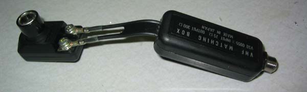
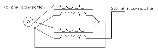
What is needed here is a device which will pass the RF from the antenna to the receiver while at the same time blocking low frequencies (in particular the 60 Hz power line frequency). One simple method is to put to 300-75 ohm Baluns "back-to-back". Such as this
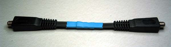
Or, here's another varient of the same idea. (There are two solderless splices under that blue heat shrink to connect the two conductors together, hopefully with minimal impedance change.):
I made this particular unit out of parts I had laying around, but similar matching transformers are available at most electronics supply stores and even Radio Shack.
The problem is that it seems that a lot of these sort of Baluns are NOT isolating.
This is easy enough to test with a multimeter. Test for continuity between the shield of the 75 ohm connector and either of the connections on the 300 ohm side. In this case I got lucky -- the balun on the left is isolating. However the other one on the right is not. I tested the 6-8 units I had in my grab bag of these and only found this one that provided the needed isolation.
Solution #2 (build your own):
Fortunately baluns like the one on the right provide most of the parts needed to make a isolation transformer in a neat package. All that is needed in addition is a short length of 75-ohm cable (preferably the smaller easier to work with RG-59 type), and an "F" connector. (You also need reasonable mechanical and soldering skills).
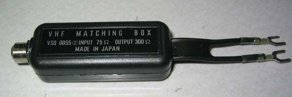
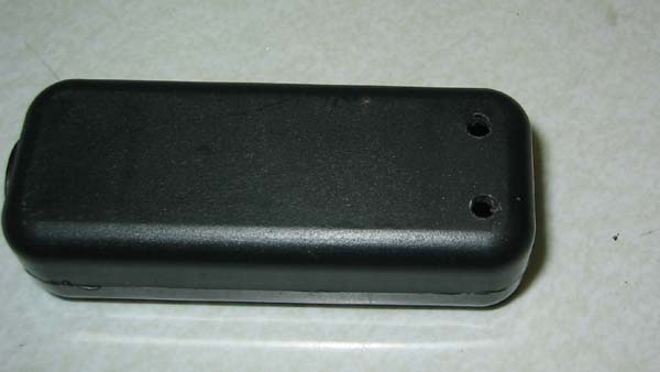
Start by buying a Balun of the sort seen here:
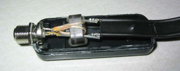
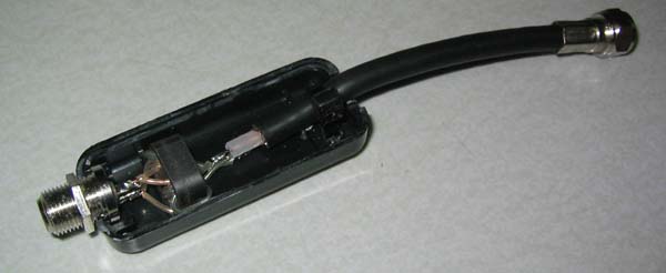
Very carefully crack open the plastic case. The technique I use it to put a knife blade to the seam between the plastic halves and push down firmly. This will crack the glue but leave you with halves that are still serviceable. Once open you'll find something like this:
This particular unit has what is known as a "Guanella balun" which has the following schematic:
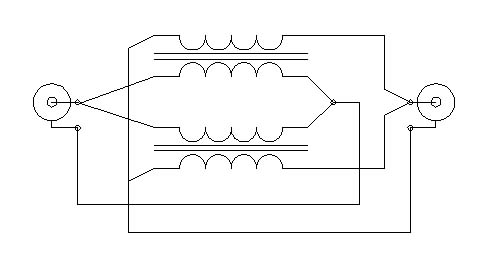
It's worth studying whatever unit you open for there are other ways to build baluns. This is the most common however. What we want to do is rewire this to become two 1:1 isolation transformers in parallel like this:
The easiest way to do this is to cut the core completely free from the connectors so that you're left with something like this:
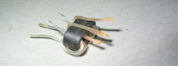
Note that the windings are made from "zip cord" that is two insulated conductors bonded together much like the common power cords for table lamps and the like. Conveniently, one of the two conductors is left in it's natural copper color, and the other has a nickel plating to give it a silver color. This makes the windings easy to tell apart.
Now you need to carefully rework the wires so that come out on the correct side. You want all of the copper colored ones to come out one side and all of the silver colored ones to come out the other. You also want to insure that the copper and the silver wires make the same number of turns through the the core. You will also need to be sure that the two windings are "in phase". This means they should be symmetric -- If the center conductor for one winding is going through the center on one side of the core, it should be the same for the other winding. Here's a picture of the reworked core reconnected to the original female "F" connector on the right, and to a new piece of RG-59 on the left.

The other end of the RG-59 has a Male "F" connector.
It's time to test. Carefully install the assembly in series with the antenna connection on your receiver or TV and check two things -- Your signal strength hasn't been badly diminished, and that it actually cures the problem. I tested this one using the signal strength meter on my FM receiver with a couple of different stations and concluded it had a loss of 1-2 Db, not great, but not any worse than the Kludge you see in the first picture above.
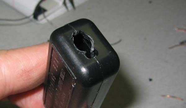
Now a couple of modifications to the plastic case. First you'll need to enlarge the opening in the end where the 300 ohm cable exited originally to accept the coax cable:
Then you should also drill a couple of smaller holes near the back opening to allow the installation of a cable tie to provide strain relief:
Finally reassemble like this: (It's difficult to see, but I've used a small cable tie to securely fasten the 75-ohm cable to the plastic case using the two small holes to thread the tie outside the case and back in, and the around the cable).
You can glue the plastic case back together with just a bit of model glue, super glue, or even hot glue. It doesn't take much. The result is a very clean looking isolation transformer that will keep your system hum free (well maybe).